The Silent Workhorse of Grid Efficiency
In the vast and complex architecture of electrical transmission and heavy industry, the high voltage capacitor unit operates as a critical, though often unseen, component for stability and efficiency. Far more sophisticated than a simple electronic capacitor, this engineered assembly is designed to store and release significant amounts of electrical energy at voltages typically ranging from thousands to hundreds of thousands of volts. Its primary roles—power factor correction and voltage support—are fundamental to reducing energy losses, improving system capacity, and ensuring the reliable delivery of electricity over long distances.
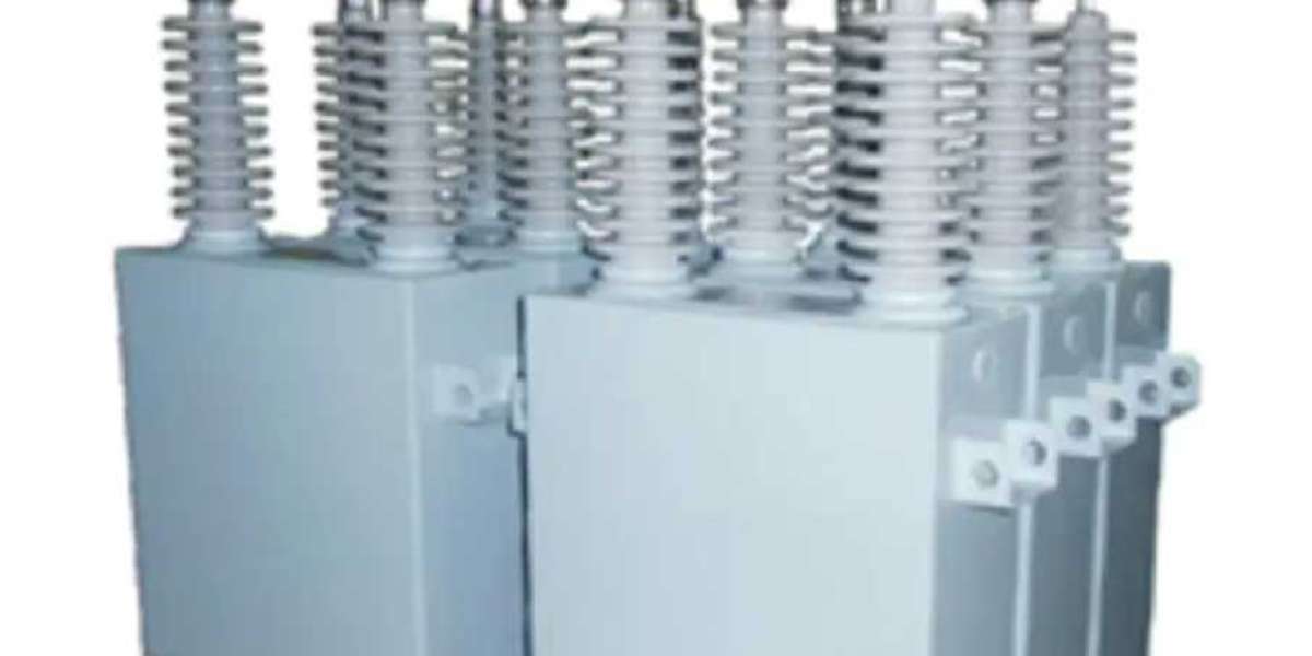
Anatomy of a High-Voltage Assembly
A single unit is not merely one large capacitor but a meticulously integrated system within a robust enclosure. Internally, it consists of numerous individual capacitor elements connected in precise series and parallel configurations to achieve the desired voltage and reactive power (kVAR) rating. These elements are immersed in a dielectric fluid, often biodegradable or non-PCB oil, which serves both as an insulating and cooling medium. The assembly includes critical internal protection devices such as pressure-sensitive disconnects that act in case of internal fault, and discharge resistors that safely drain stored charge when the unit is disconnected from the line. Bushings provide the external high-voltage connection points, making the entire package a self-contained, manageable device for substation installation.
The Physics of Power Factor Correction
The most widespread application for these units is industrial and utility power factor correction. In AC systems, inductive loads like motors and transformers cause the current to “lag” behind the voltage, creating a non-working “reactive power” that does no useful work but still occupies space in conductors, causing losses. A capacitor has the opposite effect, causing current to “lead” voltage. By strategically deploying banks of capacitor units, utilities and large factories can inject capacitive reactive power to neutralize the inductive lag. This brings the power factor closer to an ideal value of 1. The result is a dramatic reduction in line losses, decreased current on cables and transformers, and the liberation of system capacity, leading to lower electricity costs and enhanced grid performance.
Safety Imperatives and Discharge Procedures
Handling such equipment demands rigorous safety protocols due to its ability to retain a lethal charge long after being de-energized from the grid. A core safety commandment is that a unit must be positively discharged before any personnel approach. Modern designs incorporate permanent, internal discharge resistors that will drain the charge within a specified time (e.g., down to 50V within 5 minutes). However, established safety practice requires technicians to additionally short-circuit and ground the terminals using a hot stick and a safety ground before any physical contact. This two-step process—relying on internal discharge and verifying with an external ground—is non-negotiable. Regular maintenance includes checking the integrity of these discharge resistors and monitoring for signs of dielectric fluid leakage or case bulging, which indicate internal faults.